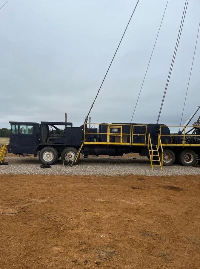
1981 Franks 1287 Workover Rig

Description
1981 FRANKS 300 Series Explorer III “Rocket” Model 1287 / 160 DTD-HT Double Drum Well Servicing Unit with 96 ft, 150,000 lb. capacity telescoping “Tri-Scope” derrick, mounted on Cabot Carrier Model 300-C powered by Detroit Diesel 60 Series, 12.7 liter, 475 HP diesel engine with Allison CLBT 4460 Transmission: MODEL 1287 MAIN DRUM WINCH ASSEMBLY: With full air clutched single speed jackshaft for single speed main drum drive; 42” x 12” brake rims, removable stress-free type mounting with lips for water cooling. Single point adjusted and equalized full wrap brakes with high advantage linkage and roller type release. Full air, plate type final friction clutch developing 41,000# single line pull. Dynamically balanced drum with 18 7/8” O.D. drum barrel 34” long, roller bearings mounted on live drum shaft. Oil bath chain drive to drum. Centralized lubrication. Plate construction winch frame with easy removal steel guards. POCKET IN MAIN DRUM: For rope socket line tie back. MODEL 160 SAND DRUM ASSEMBLY: Capacity 16,000 ‘of 9/16” line; 42” x 8” brake rims, removable stress-free type mounting with lips for water cooling. Single point adjusted and equalized full wrap brakes. Full air, plate type final friction drive clutch with capacity to develop 29,000# single line pull. Dynamically balanced drum with 13 ¼” x 42” drum barrel. Plate construction frame with steel guards and splash guards. Centralized lubrication. Sand drum is two-speed with two-speed main drum assembly. Self-holding jaw type clutch at sand drum drive input sprocket provides total disengagement of all sand drum drive components except when swabbing. MODEL 450 HIGH-SPEED RIGHT-ANGLE GEAR BOX: Large spiral bevel gears in cast gear case, integrally mounted to winch. Single speed chain drive to winch in leakproof oil bath case. Thru-shaft provided with internal disconnect and controls for bogie drive. Includes input propeller shaft from transmission to right angle gear box and propeller shaft from right angel gear box to bogie. BRAKE COLLING WATER PRESSURE SYSTEM: 60-gallon reservoir and system. Includes reservoir with safety filler, air pressure drive and water piping of 3/8” tubing from reservoir to main drum and sand drum brake rims. Water piping complete with control valve at operator’s position and with selector valves. Also has cut off valve at reservoir to shut off all pressure to tank and blow down water lines for winter operations. 15” DOUBLE ROTOR PARKERSBURG HYDROTARDER BRAKE: Low mounted on off-operator’s side of unit. Chain drive in oil bath case. High speed positive air actuated drive clutch with control valves and pedal control at operation’s position but less water system. Can be used with main drum or sand drum. HYDROTARDER WATER RESERVOIR: 250-gallon capacity, bed mounted, including inlet and return lines from reservoir to hydrotarder. OPERATOR’S PLATFORM: Alongside of unit. Hinged folding type, of diamond floor plate, with self-storing ladder. For main drum and sand reel operations, cat heading and deck access. FRAME AND REAR BED: Integral framing for mounting winch to chassis. Rear bed with full width steel deck behind winch. Front bed with steel deck full width ahead of winch. Engine drive guard, chassis width. MUD FLAPS: Back of rear wheels. Set of two. HYDRAULIC SUPPORT LEGS: To remove weight of unit from springs and tires, providing greater lateral stability. CONTROLS FOR DOUBLE DRUM, SINGLE SPEED DRIVE: Main drum controls located at rear of unit and sandreel controls along side winch. Includes air control valves for main drum clutch, sandreel clutch, single speed jackshaft, master clutch (where applicable), foot pedal engine throttle, handset engine throttle at sandreel position, and air system complete with wet-dry reservoir, air line lubricator, and strainers, air lines and air pressure gauge. Mechanical brake levers. CONTROLS AT REAR FOR DERRICK UNITS – 4’6” POSITION WITH PLATFORM ON DERRICK LEG: Includes folding platform hinged to derrick leg, and ladder with handrail. Allows brake lever to pivot at derrick hinge point during raising or lowering of derrick without removing brake linage. Includes provision for engine throttle control at derrick hydraulic raising and lowering control location. HYDRAULIC POWER TONG DRIVE INSTALLATION (CLUTCH TYPE), LESS TONGS: System designed to operate up to 2000 PSI at 30 fpm intermittent duty. Includes increased capacity pump and drive with full air friction clutch for pump disconnect, increased volume reservoir, oil, lines, filter, quick disconnect couplings, pressure regulator valve, tong selector valve and throttle speed set with tong control at operator’s position. DERRICK: 96’, 150,000# capacity “Tri-Scope” telescoping derrick with legs of cold drawn seamless alloy heat treated steel tubing selected for designated height and load capacity. Electric welding exterior and interior bracing to produce a structure of exception torsional rigidity. Constructed in two sections, the upper section telescoping into the lower section for transporting over the road. Franks patented device for locking derrick into fully extended position consisting of pawl and lug mechanism operated automatically without need for bolts or any other fastening. Adjustable support screws in derrick legs; folding ladder, level and tilt indicator. Raising hinge blocks with composition bearings. All derricks include attachment points for four wind guys from crown to ground and two wind guys from racking board to ground per appropriate Cabot recommended guying designs. HYDRAULIC RAISING, LOWERING AND EXTENDING: Once double action, three stage, telescoping type hydraulic raising and retracting cylinder. Hydraulic pump with drive, complete with all lines, valves, oil reservoir and fluid. Two stage, single acting extending cylinder. DERRICK SUPPORTS: Front and rear, with quick detachable hinge point clamps for easy removal of derrick from unit. FIVE-SHEAVE CROWN BLOCK ASSEMBLY: Integral type, welded box construction; 25” O.D. sheaves with hardened grooves mounted on two deep-grove, high-capacity ball bearings per sheave; hardened, ground sheave pins with locking pins, spacers and zerk fittings for greasing all sheave bearings. Includes offset sheave for fast line. CATLINE SHEAVE: At water table. RACKING BOARD: All welded construction with derrickman’s adjustable platform of expanded metal. Racking fingers are furnished to facilitate uniform racking and to prevent swarming and have locking pins at open ends. Folds over the derrick in over the road position. Maximum capacity 22,500’ of 2 3/8” or 13,200’ of 2 7/8” tubing in double stands of range 2. VERTICAL ADJUSTMENT OF RACKING BOARD: Standard and one additional position. AUTOMATIC UNFOLDING AND FOLDING OF RACKING BOARD: During extension and lowering of upper section of derrick. CROW’S NEST: With guard rail and expanded metal floor. AIR LIFT ROD TRANSFER: Includes air cylinder, foot operated control valve, air regulator, sorage box for foot pedal, lift cable, pulleys, and three safety rod transfer elevators; one for 5/8” rods, one for 3/4” and 7/8” rods and one for 1” rods. AUTOMATIC FOLDING COMBINATION ROD HANGER SUPPORT AND PLATFORM: Includes rodman’s folding platform with guard rails, mounted below level of rod hangers, hinged to derrick so that rod board automatically lowers when derrick extends. Provisions for two Paramount Rod Hangers. ROD HANGERS: One pair #104 with adapter sleeves for 5/8”, 3/4”, 7/8”, & 1” FRONT GUY LINE ANCHORAGE: Anchored to front of Explorer Carrier; includes cables, tail chains, forged steel boomers, thimbles, and clamps. LIGHTING SYSTEM: Fluorescent lighting system of weatherproof type, neoprene jacketed cable rigidly attached to derrick structure. Two double tube units lighting floor area, one double tube unit lighting drawworks and four single units lighting racking board area. Shielded bulb at crown. Circuit breaker and junction panel located at operator’s position. AC Current Only. Includes guards to protect lights from cables. DEADLINE ANCHOR: Attached to main frame. Including Ratigan Becket for quick disconnect of deadline anchor. CABOT CARRIER MODEL 300-C: Tandem front, tandem rear carrier with 8 x 4 drive, 275” tandem center to tandem center wheelbase. 20” deep fabricated composite channel high strength chassis, all welded construction. Shuler FK tandem front axles (39,000# service rating) with 17 ¼” x 4” air brakes on all wheels and with Reyco spring suspension. Eaton 38DP double reduction (45,000# service rating) rear tandem axles with 16 ½” x 7” air brakes, walking beam suspension. Bendix-Westinghouse DD3 safety brakes mounted on forward rear axle. 8V-71N Detroit Diesel engine, Allison CLBT 4460 transmission, Bendix-Westinghouse TuFlo 1000 flange mounted air compressor, variable speed governor, 12-volt group 8D batteries, mechanical radiator shutters, horn warning system for engine high water temperature or low oil pressure, 8.38 ration (straight thru drive). Disc wheels, four 15:00 x 22.5 16-ply duplex highway tread front tires, eight 10:00 x 20 12-ply nylon all-purpose treat rear tires, spare rear wheel. Ross TE71 steering with Garrison hydraulic power assist. Easy service one-man cab with heater, defroster, two bus type rear view mirrors, driving instrument panel and adjustable bucket seat with shock absorber mounts and seat belt. Mechanical tachometer and duplicate engine instruments mounted in panel behind cab. Model 750 Luberfiner oil filter. DIESEL TANKS: Two 125-gallon capacity. CATHEAD: Franks manual, large drum with safety guard and foul free integral hub. Mounted on operator’s side of unit, within 8’ road limits. FRANKS GROOVED DRUM JACKET: 1287 Line saver grooved spooling jacket, removable in halves. For regular spiral spool-on of first wrap of line. 1” grooving FRONT TIE DOWN FOR EXPLORER CARRIERS: With hook for carrying over th road TOOLBOXES: Two 18” x 18” x 36” sheet steel CLEARANCE AND DIRECTIONAL SIGNAL LIGHTS FOR EXPLORER MODEL UNIT: Includes heavy duty oilfield construction reflectors and recessed, protected bed lights, mast or derrick detachable load light in addition to cab lights furnished on carrier and directional signal lights TUBING TONG POSITIONER: For moving hydraulic tubing tongs from standby position on to tubing in working position. Air operated adjustable in height from 3’ above ground. Pivot shaft installed inboard of front derrick leg to swing tongs from face of derrick outward to well center. Swing arm length adjustable. Air control valve at operator’s control station. AIR SLIP CONTROL: Consist of control valve and air pressure regulator in control box or control panel. TOOLS: Available Guiberson bells and rod elevators. Foster Rod and Tubing Tongs
Specifications
| Manufacturer | Franks |
| Model | 1287 Workover Rig |
| Year | 1981 |
| Condition | Used |
| Serial Number | 720066 |
| Stock Number | 00067 |